A PNG tree is pixels. A CAD block is geometry with a name, a base point and a real size, inserted once and repeated at 1:1 across the drawing. Tracing is only the conversion — scaling and blocking are what make it usable. Three routes below end in the same place: a .dwg in your block library. Start with the first one, because the cheapest block is the one you do not draw.
Route A — Download and reuse
Somebody already drew it. Two libraries to download sit below. Fastest by far, until the one you need is missing.
Route B — Illustrator Image Trace
Visual, one tree at a time, full control over how much detail survives. Use it for a symbol you will look at closely.
Route C — Claude Code
Yes, this works in code, and you never touch a terminal. Best when twenty silhouettes need identical treatment.
Route A — Download and reuse
The fastest block is the one somebody already drew. Entourage libraries circulate freely, and a competent drafter starts by looking for one rather than tracing. Two to start with, trees for AutoCAD and people and cars for Rhino:
Open the donor file first
Open it on its own and look before you borrow. Run DIST across something you can size by eye — a person is about 1.75 m, a car about 4.5 m long. That one measurement tells you the file's units, which is the thing that goes wrong most often.
Bring the block across
- AutoCAD. Copy the block you want, then PASTEBLOCK into your drawing. Or use DESIGNCENTER to pull single blocks out of the donor file without opening it.
- Rhino. Insert for a block instance, Import to bring the geometry in loose.
- Re-measure after it lands. If it came in at the wrong size, SCALE with the Reference option against a dimension you know.
Clean up what you inherited
Borrowed files carry layers, text styles and dimension styles you never asked for. Run PURGE and then AUDIT after inserting. If the block will become part of your own library, redefine it on layer 0 with colour ByBlock and a base point you choose.
For anything beyond these two, three places are worth a look before the general block sites: manufacturers publish blocks for their own benches, bollards and light fittings; city open-data portals carry street trees and curb geometry; and your studio's past projects already hold blocks someone on your floor drew and can vouch for.
Before you trace — prepare the PNG
Get a clean silhouette
Tracing reads contrast, so the quality of the trace is decided before Illustrator opens.
- High contrast. A dark tree on a white or transparent background. A photograph of a tree traces into mud.
- Big enough. 1000 px or more across the canopy. Tracing a 200 px thumbnail bakes the pixel staircase into your curves.
- Cropped. Anything else left in frame becomes geometry.
- Real size known. Decide the canopy diameter now — say 6 m for a street tree, 12 m for a mature oak. You need that number twice below.
Route B — Illustrator → AutoCAD
Place the image
File → Place, with Link unchecked so the pixels travel inside the file.
Image Trace
Select the image, open Window → Image Trace, start from the Black and White Logo preset, then open Advanced:
| Setting | What it does |
|---|---|
| Threshold | The cutoff between black and white. Raise it to capture more canopy, lower it to drop grey noise. The single most important slider. |
| Paths | How tightly curves hug the pixels. Lower gives smoother, lighter geometry; high values produce thousands of vertices that make AutoCAD crawl. |
| Corners | How readily a curve becomes a sharp corner. Keep it low for foliage, high for hard-edged symbols. |
| Noise | Ignores blobs below this pixel count. Raise it to kill speckle. |
| Ignore White | Check it, or a white rectangle rides along behind the tree and arrives in CAD as a solid. |
Watch the path count at the bottom of the panel. A few hundred paths is healthy for a plan symbol.
Expand and simplify
Object → Expand turns the live trace into real paths. Then Object → Path → Simplify, pulling the slider down until the shape is about to change — that point is your vertex budget.
Delete leftover white shapes and stray specks. Set fill to none and stroke to black so you can see the outlines you are actually exporting.
Export DXF
File → Export → Export As, format AutoCAD Interchange File (.dxf). In the options: version 2007 or later, 1 unit = 1 mm, Preserve appearance off, Outline text on.
Scale to real size
Open the DXF in AutoCAD, select everything, run SCALE and take the Reference option: pick the two edges of the canopy, then type the real canopy width. The tree now measures what a tree measures. Confirm with DIST before going on.
Make the block
- Move the geometry to layer 0 and set colour, linetype and lineweight to ByBlock. That is what lets the block take on the look of whatever layer you insert it on.
- Run WBLOCK, base point at the trunk centre — the point you will snap to survey coordinates.
- Name it for what it is and how big it is: TREE-DECID-06M.dwg, saved in a blocks folder beside the project.
Route C — Claude Code, no Illustrator
Tracing is contour-finding, and contour-finding is a solved problem. You do not need Python, pip or a command prompt for this — Claude Code installs what it needs, writes the script and runs it for you. You supply the tree, the real size and the judgement. Set Claude Code up the way WF07 describes, then:
Make a folder
Put your silhouette PNGs in it, plus the spec file below. Open Claude Code in that folder.
↓ Download the build spec — png2dxf-spec.mdAsk in one line
The spec carries the detail — libraries, contour mode, base point at the trunk, geometry on layer 0 — so your prompt stays short. That division is the lesson: write the standing requirements down once, ask in a sentence.
Keep talking
The first result is a draft. Say what is wrong in plain language:
Open the DXF in AutoCAD and the block is already defined, already the right size, already built on layer 0. Run WBLOCK once to write it into your library.
Things that go wrong
| Symptom | Cause and fix |
|---|---|
| Tree arrives the size of a city block | DXF units never matched drawing units. Use SCALE → Reference against the known canopy width rather than guessing a factor. |
| Solid rectangle behind the tree | Ignore White was off during the trace. Delete the shape in Illustrator and export again. |
| Drawing crawls after inserting | Too many vertices. Re-trace with lower Paths, or ask for a simpler outline. A plan tree rarely needs more than a few hundred points. |
| Block ignores its layer colour | The geometry carries an explicit colour. Redefine it with everything on layer 0 and colour ByBlock. |
| Trees refuse to land on the survey point | Base point sits at a canopy corner. Redefine the block with the base at the trunk centre. |
| Canopy holes come in filled | The trace kept outer contours only. In Illustrator select all paths and use Object → Compound Path → Make. |
Worked examples
Two traces, source beside result.
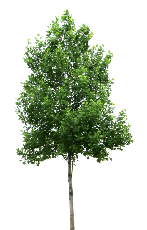
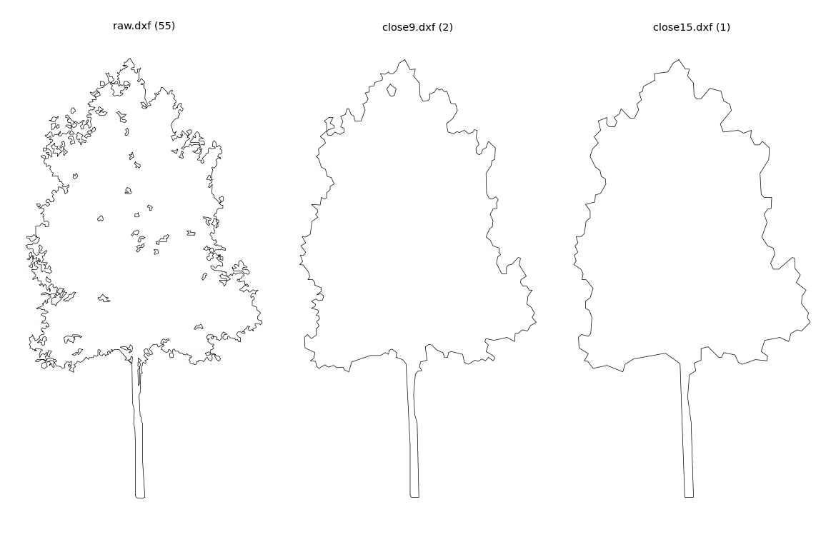
One photographic tree
Four trees in one image
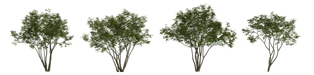
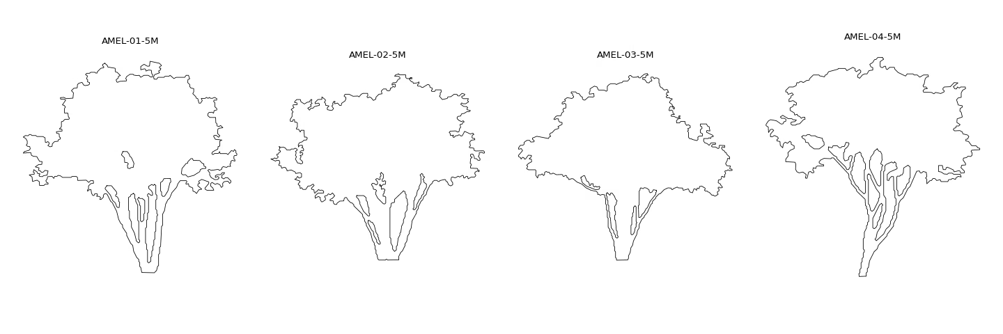
One image, four blocks: split the trees apart first, and keep the close light so the multiple stems stay open.