EXTRA
Ramp on a Slope
An accessible route up a hillside · Section first, plan second · Rhino 8
▶
Video — Two Ways to Model a Ramp
A narrated recording, with chapters and captions (CC). When you know the elevations at both ends, Sweep1 the sections along the centerline. When you know the centerline and the slope, build the ramp straight and Flow it onto the curve. Each method is shown in Rhino and in Grasshopper. Both are for testing ideas quickly; the steps below do the ADA math.
LengthSelf-paced
Site100'×100', rises 30'
Code2010 ADA Standards §405
ToolRhino 8
Learning Objectives
- Reading a code as geometry: slope, rise and length
- Designing in section and plan at once
PracticeDesign an accessible route up a 100'×100' slope that rises 30': a stretch-out profile, a plan, and a Rhino model that passes the checks in Step 07.
Rise
→
Length
→
Plan angle
→
Switchbacks
→
Rhino
→
Check
A ramp is a long, thin strip of constant grade folded onto a site. You design it twice at the same time: in section, where the code is checked, and in plan, where it has to fit. Work out the section first, because it tells you how much ramp you need. The plan then tells you whether it fits.
The numbers below follow the 2010 ADA Standards. Your local code may differ; check it on a real project.
01
Read the Slope
Measure two numbers: the rise (how much higher the top is) and the run (the horizontal distance). Slope is rise ÷ run. This site rises 30' over 100', a 30% slope, more than three times steeper than a ramp may be.
02
Learn the Ramp Rules
1:12 means 1' of rise for every 12' of horizontal run. A ramp may be 1:12 or flatter (1:14, 1:16), never steeper (1:10). Every number in the table below shapes the drawing.
| Rule | Value | § |
|---|---|---|
| Running slope | 1:12 (8.33%) or flatter; use the least slope you can | 405.2 |
| Cross slope | 1:48 (2%) or flatter | 405.3 |
| Clear width | 36″ minimum between handrails; 5' lets two people pass | 405.5 |
| Rise per run | 30″ (2.5') maximum, then a landing | 405.6 |
| Landing | 60″ long, as wide as the ramp, level | 405.7 |
| Turning landing | 60″ × 60″ minimum where the ramp changes direction | 405.7.4 |
| Handrails | Both sides once rise passes 6″; 34–38″ high, continuous on the inside of a switchback, extend 12″ past the top and bottom | 405.8, 505 |
| Edge protection | A curb or barrier so a wheel cannot roll off | 405.9 |
| Walk, not a ramp | A surface at 1:20 (5%) or flatter is a walk: no landings or handrails required | 402, 403.3 |
03
Calculate the Minimum Length
Before drawing anything, find out how long the ramp has to be. Pull the whole route out straight and draw it from the side: this stretch-out profile is where the rules are checked.
rise H = 30'
sloped run = H × 12 = 360' (ramp at 1:12)
runs needed n = ceil(H ÷ 2.5) = 12 (each 30' long)
landings = (n − 1) × 5' = 55'
top + bottom = 2 × 5' = 10'
minimum path = 360 + 55 + 10 = 425'
425' is the floor. Real designs run longer:
| Factor | Adjustment | This site |
|---|---|---|
| Design at 1:13 | Room for construction tolerance; the code allows none | +30' |
| Switchback turns | A 180° turn landing is about 11' of centerline, not 5' | +6' per turn |
| A walk at 1:20 | No landings or handrails | 600' |
For any site: minimum path ≈ H × 12 + 5 × (ceil(H ÷ 2.5) − 1) + 10, in feet, plus 6' for each 180° turn.
04
Find the Plan Angle
The ramp climbs gently by crossing the hill at an angle. Walking along a contour, you stay level. Walking straight up, you climb the full slope s. Turn the path an angle α off the contour and only the uphill part of each step climbs, the sin α share:
g = s · sin α → α = asin(g ÷ s) = asin(0.0833 ÷ 0.30) ≈ 16°
Drag the slider. The path turns green at 1:12 or flatter.
16°
sin α rise over 60' grade 0.30 · sin α
The formula needs one constant slope. On real terrain, step it out contour by contour instead: a circle of radius Δh ÷ g, centered where the run starts, marks where it reaches the next contour.
05
Fold It into Switchbacks
A 425' ramp does not fit across a 100' site, so it turns back on itself. Split the profile into legs of run, landing, run (65', rising 5'). Six legs climb 30'.
Turn landings move the path uphill without climbing, so the legs cross the hill at a flatter angle than 16°. Solve for it with a Y budget: the legs and turns together have to cover the 100' of uphill distance.
Draw the plan from the same pieces as the profile, at exact lengths, and the two drawings match by construction. Rhino's cylindrical input
@length<angle,rise draws plan and profile in one line. The angle is measured counterclockwise from +X: legs heading right use α, legs heading back use 180° − α.Polyline
14,0,0 start, bottom of the site
@30<10.3,2.5 run
@5<10.3,0 landing
@30<10.3,2.5 run
@2.5<0,0 into the turn
@6<90,0 across: 5' ramp + 1' gap
@2.5<180,0 out of the turn
@30<169.7,2.5 next leg, heading back
… repeat; the last point lands at 14,100,30
06
Build It in Rhino
Rhino
- Site. Set units to feet.
SrfPt0,0,0 → 100,0,0 → 100,100,30 → 0,100,30 makes the slope. - Contours.
Contouron the site, direction Z, interval 2.5. Each line is one run's worth of rise. - Centerline. Type the polyline from Step 05 on its own layer.
- Ramp surface. Draw a 5' horizontal line square to the path at its start.
Sweep1with the centerline as rail and the line as section, Style Roadlike Top, so the surface stays level edge to edge. - Cut and fill.
Intersectthe ramp with the site. Where the line runs, ramp and ground meet; uphill of it you cut, downhill you fill. Plan a retaining wall where the cut passes about 1'. - Handrails.
DupEdgethe two long edges,Movethem up 3',Extend1' at each end, thenPipeat radius 0.0625' (a 1½″ rail).
07
Check Before You Present
Grade.
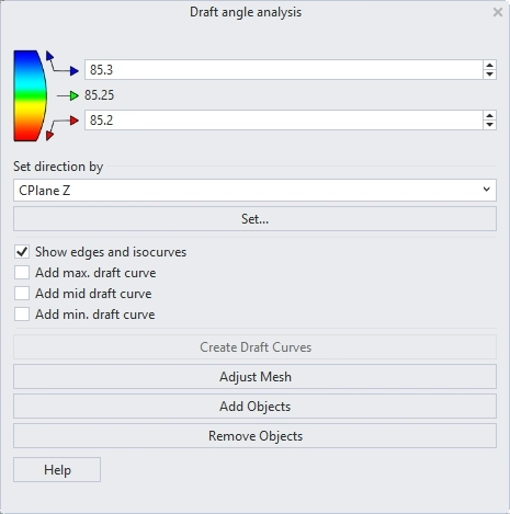
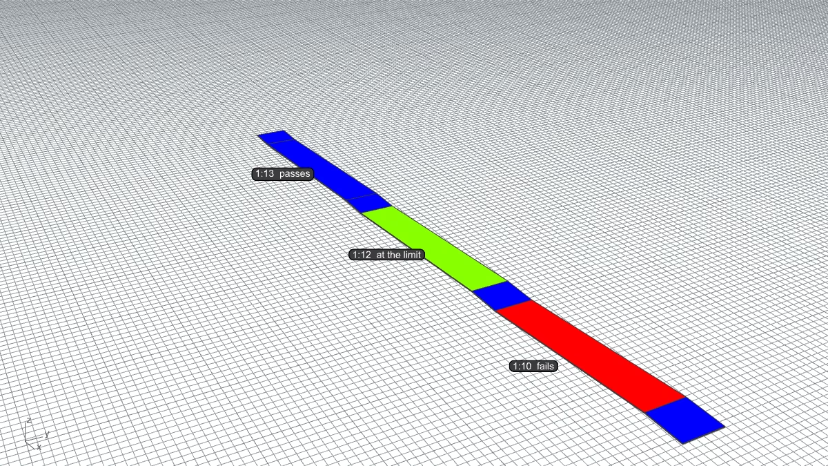
DraftAngleAnalysis colors a surface by its steepness: the angle between the surface and the up direction, 90° for a flat floor, 0° for a wall. Draft angle = 90° − slope angle, so a 1:12 ramp reads 85.24°. Rhino paints everything below the lower number red and everything above the upper number blue, so set the two numbers close around the limit and the map turns into pass or fail.- Select the ramp, run
DraftAngleAnalysis, keep the direction at CPlane Z. - Type 85.3 in the top box and 85.2 in the bottom box.
- Blue passes, red fails, a green band sits right at 1:12. Flat landings read blue too.
- For an exact number at one spot, run
DraftAnglePointand pick on the surface.
| Checking for | Limit | Bottom | Top |
|---|---|---|---|
| Ramp at the code limit, 1:12 | 85.24° | 85.2 | 85.3 |
| Ramp with tolerance, 1:13 | 85.60° | 85.55 | 85.65 |
| Walk, 1:20 | 87.14° | 87.1 | 87.2 |
Then the rest of the list:
- Plan length, not 3D length.
Lengthmeasures in 3D, so a 30' run reads 30.10'. Check a flattened copy (Projectto the CPlane). - Rise per run. 2.5' or less between landings.
- Landings. 5' long; turn landings at least 5' × 5' and as wide as both ramps at a switchback.
- The top. The path ends at elevation 30' on the top edge of the site.
- Walls. Every cut over about 1' has a wall drawn in plan and section.